Lalit Saini
Designing of S.M.I.F POD Opener
S.M.I.F POD Opener would be used as stand alone equipment for opening POD for open cassette semi-conductor tool and can be placed and positioned anywhere.
The purpose of the SMIF Pod Opener is to lock and unlocked the POD, which would be placed over the top surface of it. And it would be achieved by rotating the latch up to 86 degrees as per specified by the SEMI standards.
The plate with the latch pins rotates clockwise by 86°, thus unlocking the pod door from the pod body. Concurrently, the two hold-down movers linearly pushed out, thus preventing removal of the pod body. The plate with the latch pins rotates anticlockwise by 86°, thus locking the pod door to the pod body. Concurrently, the two hold-down movers pushed in, thus releasing the pod body.
1. Advantages and Disadvantages
ADVANTAGES
-
SMIF Pod Opener provides the easier way to open and close the SMIF Pod without using the whole setup i.e. SMIF Loader.
-
It would be controlled with two push buttons, one for rotating the latch clockwise and one for anti-clockwise.
-
It can be placed anywhere without any size restrictions because it has the dimensions of 286 mm x 276 mm x 25 mm, as per SEMI Standard E15.1.
-
It would be operated with 12 volts adapter.
-
Material used has least particle count which is required in the clean room environment.
DISADVANTAGES
-
Manufacturing cost is high due to the complexity of design.
-
Material cost is high, as material used should be clean room compatible.
2. Future Applications
-
SMIF Pod Opener can be very useful tool for the opening and closing of POD Door in the absence of the SMIF Loader Machine.
-
Pod opener is mainly required in metrology tools where SMIF interface is not possible either due to absence of proper interface in machine or due to space limitations.
3. Designs
The main objective is to rotate the latch up to 86 degrees which will open and close the POD Door and making the linear motion of locking bolt up to 10 mm which will lock and unlock the POD on the surface of Port plate.
OPTION 1
A. DESIGN CONSIDERATIONS
-
Pod Opener should be aligned with the Pod Door.
-
Registration Pins should be located and placed precisely over the Pod Opener, so that it
would be perfectly aligned with the Pod Door.
-
Position of Latch Pins on the latch should be at 20 degrees from the X axis, as discussed above.
-
Design should be compact and clean room compatible.
-
Material should be chosen on the basis of high quality, minimum particle release and has
resistivity to corrosion.
-
It should be designed within the plain view of 286 mm x 276 mm as per SEMI Standard E15.1. These standards are developed and maintained for the interchangeability of machines and designs without any alterations.
-
Mechanism for locking and unlocking the POD body should also be introduced while
rotating the latch.
B. TORQUE CALCULATIONS
The DC Motor torque required for rotating the latch upto 86º as well as for linear motion of locking bolt is calculated by assuming the torque and RPM at CAM including the friction part and load, and that is 4.73N-m and 6 RPM, which is required torque for rotating the CAM with applied load. Gear head would be assembled with the CAM to attain the required torque. Calculations regarding the RPM and Torque at the one end of gear head are as below.
The arrangement of gears in gear head would be like this:
CAM Design
Assuming CAM requiring torque and RPM as 4.73 N-m and 6 respectively, RPM of spur gear can be calculated by using the mathematical relation that torque is inversely proportional to RPM.
Torque (cam) / Torque (spur) = RPMspur / RPMcam ………….1
Also number of teeth on a gear is inversely proportional to the RPM of the gear.
Teeth (cam) / Teeth(spur) = RPMspur / RPMcam …………..2
Using the above relations, toque required at the Spur gear can be calculated. Let’s take the number of teeth at CAM and Spur gear as 90 and 12 respectively. For 90 number of teeth, diameter of CAM should be approx. 92 mm with pitch 3.2 mm.
Spur and Helical Gear Design
Using the relation 2, RPM of spur gear can be calculated and it comes out to be 44. And using this value in the relation 1, toque at Spur gear comes out to be 0.645 N-m.
As it is clear from the figure 5.3, spur gear and helical gear are on the same shaft, that is, it is a compound gear. In compound gear RPM and Torque are same on both the gears.
Therefore, Torquehelical = Torquespur = 0.645 N-m
RPMhelical = RPMcam = 44
Worm Gear Design
Now, torque required at the worm gear, which is mated with the helical gear is necessary to calculate the requirement of motor.
Considering standard pitch of Worm Gear as 3mm. It means that in one rotation of worm gear, the helical gear will get displaced 3mm.
Taking the standard dimension of helical gear, pitch circle diameter of helical gear as 18mm, circumference of helical gear could be calculated with simple formula as πd, where d is pitch circle diameter of helical gear. It comes out to be 56.52mm.
Now, rounds of Worm gear required for one revolution of helical gear, can be calculated as,
Circumference of Helical Gear / Pitch of Worm Gear
Using the above relation, 19 rounds of worm gear required for the one revolution of helical gear.
Therefore, RPMworm = RPMhelical X 19 = 830
Torque required at the worm gear can be calculated with the relation 1.
Torque(worm) / Torque(helical) = RPMhelical / RPMworm
After putting the values obtained in the given equation, torque can be calculated, which comes out to be 0.0345 N-m. This is the required torque at the shaft which is connected with the worm gear.
C. MOTOR SELECTION
As the required torque at the shaft is 0.0345 N-m, so motor should be selected on the required torque. Finally, DC Motor has been selected having the RPM 9800 and torque 0.0029 N-m with a initial gear head with gear ratio 11.9: 1 which absolutely matches with the desired torque.
D. GEAR SELECTION
The arrangement of the gears would be like, as described in the figure 5.3. Taking the torque and RPM into considerations, size and diameter of each mating gear is obtained.
CAM diameter should not be exceeded more than 100 mm due to dimensional constraints. Keeping view of the complexity and shape of the SMIF POD Opener, CAM diameter is selected as 92mm having 90 tooth with 3.2mm pitch. It is not a standard size, therefore it would be designed and manufactured.
Helical gear, Worm gear and Spur gear sizes are taken as the standard sizes with the required calculations.These are not designed but are easily available in the market.
E. PHYSICAL STRUCTURE
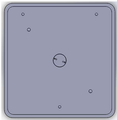
Top View of POD Opener
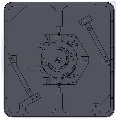
Bottom View of POD opener
Isometric Views
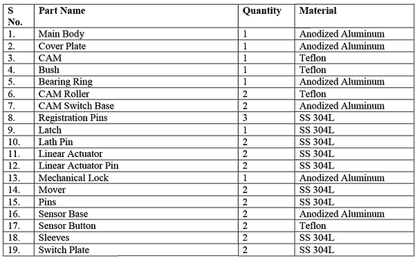
F. PARTS LIST
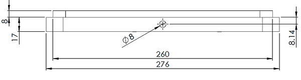
G. PARTS DRAWINGS
a. Main Body: Main Body is the main frame of the SMIF POD Opener, on which all other parts are assembled. The dimensions are chosen according to SEMI standard.
b. Cover Plate: Cover Plate is the part which would cover the bottom of Pod Opener.
c. CAM: CAM is the major and important part in the POD Opener because this is only part which would make the latch rotate, as well make the linear motion of actuator. This is done with the help of slots cut in CAM. These slots will make the linear actuator to follow linearly according to the direction of slots cut in CAM.
d. Bush: Bush will be placed at the centre of CAM, to make the CAM stable with equal forces.
e. CAM Roller: CAM roller is used to activate the sensor during rotating the CAM.
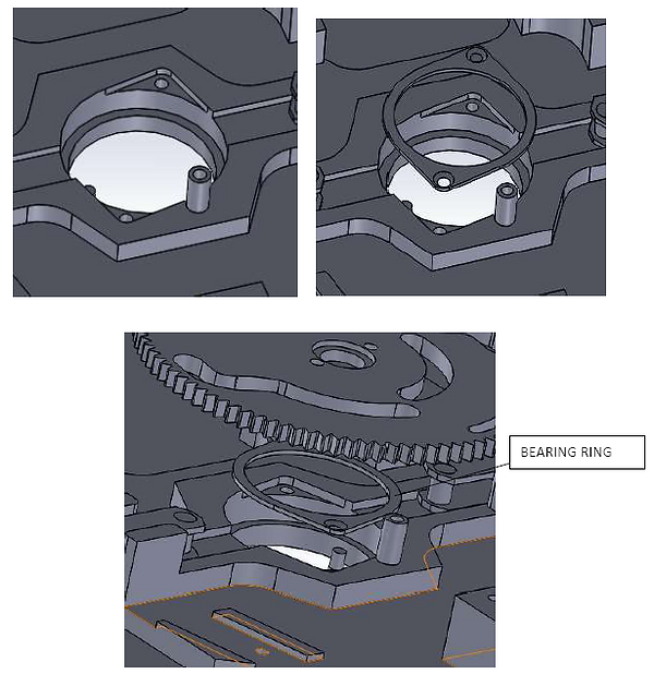
f. Bearing Ring: Bearing ring is designed to hold and grip the outer case of bearing.
g. CAM Switch Base: CAM Switch Base is designed to mount the limit switch to act as end point sensor for the CAM rotation.
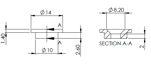
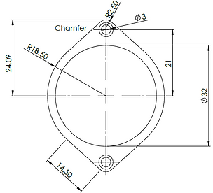
h. Registration Pins: Registration Pins would be assembled at the top surface of Pod Opener, which will be used to make the Pod registered on the top surface.
i. Latch: Latch is the assembly, which is directly coupled with the CAM. When the motor drive the CAM, the CAM will further rotate the latch up to desired angle that is 86 degree. The dimensions and location of the latch pins is the critical part while designing the latch because it should be according to the SEMI standard, otherwise it will notn match the mating holes in the POD Door.
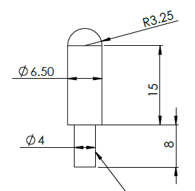
j. Latch Pins: Latch pins are the part of the latch assembly as discussed above. These pins will get fit into the hole of latch with the help of threads provided.
k. Linear Actuator: Linear actuator is the additional part assembly which would execute linear motion. It has two ends one with pinned other one is provided with internal thread for mover rod. It moves linearly when pinned end of the actuator slides inside the CAM slots. Actuator is designed in such a way that it should be free to slide linearly. It would be clear from the figure 5.4.
l. Linear Actuator Pin: Pin is used to fit the actuator inside the slot with the bearing.
m. Mechanical Lock: Mechanical lock is designed and placed at the location, where it has been into direct contact with the slot on CAM. Its purpose is to make the CAM stop, if sensors fail to work. It can be function as Emergency stop.
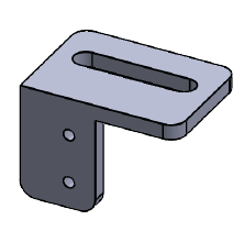
n. Mover: Mover is directly linked with linear actuator, which will help in assembly and increase the length up to the required length.
o. Sensor Base: Sensor base is the mounting for the limit switch and placed at the location, where sensor button is fitted. Its work is to sense the presence of Pod on the top surface of the Pod opener.
p. Sensor Button: Sensor button will be used to sense the Pod. The Location of sensor in the Pod is selected based on the matching projection in the Pod Door.
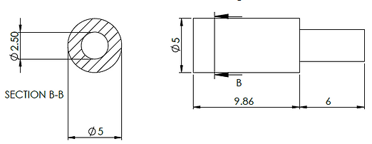
q. Sleeve: Sleeve is just like a hollow cylinder which is designed and get fitted into the long cylindrical cavity, through which mover will slide linearly. Sleeve is made up of SS304 because it does not release particle while having friction, created by mover while sliding linearly.
r. Switch Plate: Switch plate is designed, which provide marginal deflection to the switch button when pressed at the time, when POD is placed over it.
H. CHALLENGES FACED
-
Positioning and making cavities in drawing on the top face of Port Door for the registration pins was the tedious task. It was difficult to trace the location of registration pins with the help of the POD Door. It took a lot of iterations while doing measurements with the help of tools.
-
Bearing arrangement at the centre of main body was to be designed for the rotation of CAM without friction. But designing the space for the bearing at the centre took a lot of time because, bearing should not be displaced from the location; otherwise it would loosen the setup at the centre. After exploring many options, finally, it was designed as shown in figure.
Bearing Specifications
OD : 35mm
ID : 27mm
Thickness : 5mm
OPTION 2
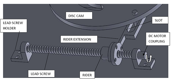
There is another mechanism to rotate the CAM. It involves the use of the Lead Screw which has been introduced in the place of Gear head which has made the mechanism simpler and less complex. The CAM in this option, has been modified in the way that the teeth have been removed, making the CAM disc shaped. Rests of the dimensions are same as the option 1 as per the SEMI Standards. Only the mechanism of rotating the CAM has been modified.
POD Opener another mechanism
As we can see, that all the outer dimensions are same. Only the mechanism and the CAM design have been replaced.
A. DRAWINGS
Gear head and CAM has been replaced with Lead Screw mechanism and Disc CAM respectively. It will be clear more with the figure as shown below.
B. WORKING OF MECHANISM
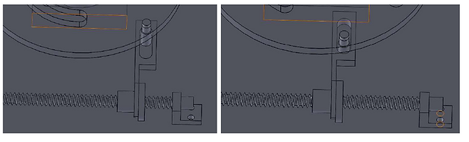
Disc CAM has a pin assembled at a certain radius as shown in the figure above.It is coupled into a slot of Rider Extension assembly with the help of miniature Bearing. Further Rider extension is bolted with the rider. When the Lead Screw is allowed to rotate with the help of the coupled motor, Rider will get displaced in one direction depending on the direction of motor rotating. Suppose when motor is rotating anticlockwise, Rider will move towards left and vice versa. At that moment, rider extension will generate the force to push the CAM in the left direction and make the pin move linearly inside the slot. As a result, disc CAM will also rotate in clockwise direction. It will be more clear from the below figures.
In the above figures, Disc CAM is made transparent to see the working of slot clearly. From the figures it is clearly visible that how the pin moves linearly inside the slot and finally make the CAM rotate.
The diameter of the Disc CAM is assumed to be 100mm for the reduction of the force applied at the Pin. The major concept is the location of the pin. At what radius pin should be assembled at the CAM so that it can bear the load on the CAM very easily.
4. Material selection
All the parts and assemblies of SMIF POD Opener should be fabricated with the materials which generate least particle count as it is the very critical in the fabrication of wafers. Secondly, it should not be corrosive. Keeping these two aspects in mind, while selecting the material, SS 304, anodized aluminum and Teflon are selected for the parts of SMIF Pod Opener.
-
SS 304L: 304 stainless steel is the most common form of stainless steel used around the world, largely due to its excellent corrosion resistance . It contains between 16 and 24 percent chromium and up to 35 percent nickel—as well as small amounts of carbon and manganese. The parts which are selected to be fabricated with SS304L are considered because those parts can be easily fabricated with the Lathe machine. Some parts which are having complex designs are not recommended to be made of SS 304, because it would be difficult to fabricate those parts.
-
Anodized Aluminum: Aluminum is a relatively soft, durable, lightweight, ductile, and malleable metal with appearance ranging from silvery to dull gray, depending on the surface roughness. Anodizing is a process to electrolytically coat a metallic surface with a protective or decorative oxide. The anodized coating is hard, durable, will never peel, and, under normal conditions, will never wear through. And another reason for aluminum anodizing is that it will not release particles.
-
Teflon: It maintains high strength, toughness and self-lubrication at low temperatures. It has no conductivity. Parts like CAM are fabricated with Teflon because these parts should be non conductive that is a non metal. It is because, it should not generate any static charge when CAM is in motion due to the friction between gears.