Lalit Saini
Robotic DUT (Device Under Test) Ladder is used for the testing of VLSI (Very Large Scale Integration) devices for SEE (Single Event Effect) test. SEE is caused by single energetic particle. In this test , VLSI devices are kept in between the path of travelling beam of high energy protons, and test data is recorded remotely for analysis.
Robotic DUT Ladder is designed to overcome the problems, which are encountered during the test. Firstly, this test is a very time consuming process, because this test is conducted into an air tight cylinder chamber (Test Port) as shown in figure, where DUT is placed inside it at the required position. Vacuum (106 torr) is maintained inside the chamber with the help of vacuum pump and test is conducted. After the test is concluded, device is removed from the test port and another device is installed. But during this, vacuum has to be generated again. So it is a lot of wastage and time consuming process.
Secondly, the value of energy of the beam and LeT (Linear Energy Transfer) to the DUT is constant. To change the LeT value, DUT has to be placed in different energy values of beam. However, Effective LeT of particular particle can be varied by changing the placement angle of device with respect to the incident beam axis. As the test port is a vacuum chamber, so tuning of the different particle energy and change of device under irradiation is excessive time consuming because for every step, vacuum have to be released and re-build. Robotic DUT Ladder is designed to overcome all the problems stated above.
1. Features of Robotic DUT Ladder
-
The main feature of Robotic DUT Ladder is that, more than one device can be loaded. It depends upon the size of the DUT which is going to be tested. It would save the lot of time while testing.
-
The DUTs can be tested at different LeT (Linear Energy Transfer) values with the beam having particular value of energy, it can be done by tilting the DUT at some particular angle and beam of particular value of energy is allowed to strike on it. It would change the amount of energy transferred (LeT) into the DUT.
-
This ladder is remotely controlled via LAN.
-
One DC motor, servo motor and optical sensor are installed into it to work.
2. Advantages and Disadvantages
ADVANTAGES
-
It would save a lot of time while testing due to its muti loading device capability.
-
Robotic DUT Ladder is compact and easy to handle.
-
It is operated at 12 volt supply only .
-
The device is portable and can easily be installed into the load port.
-
Efficiency of tilting and vertical movement is high.
DISADVANTAGES
-
Manufacturing cost is high due to the complexity of design.
-
Material cost is high.
3. Designs
It is designed on the CAD software.
A. DESIGN CONSIDERATIONS
Robotic DUT Ladder is designed, while considering some critical factors according to which design has to be propagated. These factors are:
-
The internal diameter of test port is 95mm. So, Robotic DUT Ladder is to be designed having diameter equal to or less than 93 mm providing minimum 1 mm radial clearance, so that it can be placed inside the chamber without any restriction. All the assemblies and parts are to be designed and assembled within the diameter of 93mm.
-
The overall height of the Ladder from the base plate should not be exceeded more than 350mm because of the constrained height of test port.
-
Tilting of the frame should be designed in such a way that the top surface of the DUT at which the beam will strike, should be coplanar along the axis of rotation.
It should be done so that DUT would not change its position when titled at an angle.
B. CHALLENGES FACED
-
The space existing between the test port is 95mm (diameter) which is very marginal to accommodate all the parts and assemblies. The diameter selected for the base plate is taken as 93mm, so that it can be positioned into the chamber without any restriction. But it also enhances the complexity of the design and makes it arduous to assemble the parts on the base plate.
-
The main part is the base plate on which all the major parts are assembled. The size (generally the diameters) and positioning of the parts and assemblies on the base plate are designed within the limited circumference of 93mm diameter. Also there should be no wear and tear, stress factors are also considered while designing the parts. The thickness maintained between the cavities (holes designed for parts on base plate) and the outer edge of base plate is taken as 1.5mm to maintain the strength and durability. The minimum distance between the cavities designed on the base plate should be more than 1mm for optimum strength. So, the design of base plate took a lot of time mainly in positioning the cavities.
-
The other objective laid for ladder design was the frame. The frame has to be rotated up to 60 degrees and should have the direct contact with the striking beam throughout the span of 60 degrees without any blockage. So the positioning and size of the lead screw, supporting rods as well as guiding rails should be according to the requirement as discussed above. But it is an tedious task to coordinate all the parts with optimum size and designs with the desired functional requirements. It takes a lot of iterations while designing.
C. DRAWINGS
The major parts which are designed with constraints of size are:
-
Base Plate
-
Upper Side Plates
-
Lead Screw
-
Rider
-
Guiding Rails
-
FrameFrame
-
Upper Holder
-
Frame Guide
a. Base Plate
The base plate is the core part of the assemblies. All major parts are congregate at this plate. The diameter selected for the base plate is taken as 93mm, so that it can be positioned into the chamber without any restriction. The thickness maintained between the cavities (holes designed for parts on base plate) and the outer edge of base plate is taken as 1.5mm to maintain the strength and durability. The parts which are assembled on it are, supporting rods (4 in no.), guiding rails (2 in no.), bearing for lead screw (OD 13mm), legs (4 in no.) and linear motor holding plate.
b. Upper Side Plates
Upper plates are designed to hold the parts which, are assembled on the base plate from the top face. There are two upper plates designed, one for holding the lead screw and another for holding the guiding rails. These two plates are supported by the supporting rods, which are assembled on the base plate. These are designed within constraints of size of the frame and rotation of the frame up to 60 degree. It will be much clear from figure.
c. Lead Screw
Lead Screw is designed for the Z movement of the frame through rider. The lead screw used is not a standard items, it has to be fabricated. It has the specification, having 1.75 pitch and outer diameter is 11mm.
The bearing selected has the OD of 13mm because of the size constraints of the base plate and upper side plates. The bearing ID is 6mm. Spindle will get fit into the bearing ( on both plates) and it will make the lead screw rotate without any friction.
d. Rider
Rider is used for the Z movement, when coupled with the lead screw. Rider design is very unique design in the sense that apart from main function, it has the combination of guiding pin also, so that the guiding pin will slide in between the guiding rails. Rider is coupled with lead screw at two places with little distance apart, to make the Z movement smooth without any vibrations, which is very important factor in respect of testing the DUT.
e. Guiding Rails
Guiding rails are used to make the Z movement of the frame. Guiding pin slides in between the guiding rails and make the rider stable, which will make the rider moves vertical without any rotation and hindrances. It is a hollow pipe having outer diameter 6mm. Its size is selected to reduce the weight of the ladder.
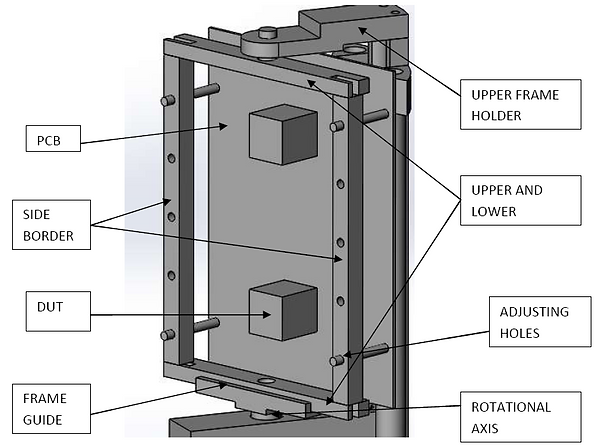
f. Frame
Frame is another important part which is used to hold the DUT(s) on which test is to be conducted. It is important because the whole frame has to be tilted up to 60 degrees and the top surface of the DUT on which the beam will strike has to be co planner with the axis of the rotation (motor axis). So it is designed in such a way, that PCB on which DUT will be assembled, get easily fit or hanged on the frame. Moreover, the width of the frame can also be adjusted as per the requirement. Frame has total 4 parts.
The distance between the Frame and PCB can be adjusted up to 20mm to make the top surface of the DUT coplanar with the axis of the rotation.
g. Frame Upper Holder
Frame Upper holder is designed to support the frame from the upper side. It is connected with the Rider from the behind of the lead screw to use the space efficiently. Frame Upper Holder has 2 parts combined to make the major part as shown in figure 5.24. There is a cavity where pin can be fitted to hold the frame when required. It is designed for the easy removal of frame.
h. Frame Guide
Frame guide is used to hold the frame from the lower side and it will guide the frame to the required angle because frame guide is directly coupled with the SERVO motor through a coupler.
i. Supporting Rods
Supporting rods are used to hold the Upper side plates at a certain distance from the base plate. It is selected having the diameter of 10 mm for sufficient strength.
D. MOTOR SELECTION
Two motors are installed into the Robotic DUT Ladder. One is coupled with the Lead Screw that is DC Motor and another is with Frame Guide which is a SERVO Motor.
Servo motor is used here because the frame has to be rotated maximum up to the angle of 60 degrees and Servo is the perfect choice for this rotation. It has the torque of 3.1 Kgcm which is sufficient for the Frame load.
DC Motor is installed to rotate the lead screw which will make the Z movement of the Frame. Also the coupler which is used to couple the lead screw and motor is designed. Three projected pins are fitted at an angle of 120° on the coupler which is sensed by the optical sensor when sweep between the sensing element, to enhance the resolution of Z movement. Finally the resolution obtained is 1.75/3 = 0.58mm.
E. MAIN FEATURES
-
Z travel: from 0 mm to 125 mm with resolution of 0.58mm and accuracy ± 0.3mm (Accuracy can be further improved by the better quality of motor used).
-
Tilt: from 0°(offset ± 2°) to 60° with resolution of 1° and accuracy ±1°
-
84mm x up to 120mm long PCB can be mounted on the frame.
-
DUT thickness (including PCB and mounting socket thickness) up to 20mm can be accommodated.
4. MATERIAL SELECTION
All the major parts are selected to be manufacture from the anodized aluminum. Aluminum is a relatively soft, durable, lightweight, ductile, and malleable metal with appearance ranging from silvery to dull gray, depending on the surface roughness. Anodizing is a process to electrolytically coat a metallic surface with a protective or decorative oxide. The anodized coating is hard, durable, will never peel, and, under normal conditions, will never wear through. And another reason for aluminum anodizing is that it will not release particles. Aluminum can easily be shaped into desired one with CNC or VMC.
Lead Screw is selected to be fabricated by the SS 304L material because it has a dynamic motion which creates the friction between the rider and lead screw, and aluminum cannot tolerate that friction to the greater extent and will get change its shape by releasing the material. So SS 304L is selected because it does not generate particles and, has excellent corrosion resistance .
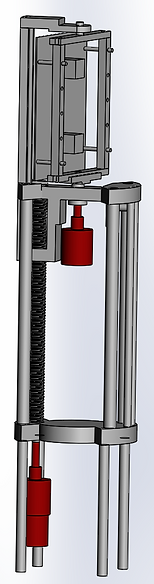
Designing of Robotic DUT Ladder

Test Port